
If you look up how to make gears, you'll find two kinds of information. The more theoretical sources talk a lot about the mathematical properties of involute curves. Most of the more practical sources talk a lot about how hard involute curves are and say you either need to approximate them using circles/button tools or use special involute cutters to cut "the exact shape".
However.
It seems to me that if we are going to be approximating anyway, it would be nice if the approximation had these properties:
The involute cutters have neither of these properties.
Why don't you care about involutes? Because the most accurate way to machine a gear is to "generate" the involute. This means you take a series of straight line cuts at varying angles, the result of which is an approximation of your involute. If you want to have the approximation be more accurate, you just take more cuts. In the limit, you have a perfect involute.
Note: I'm only covering involute spurs and racks. I think some of this either covers or can be generalized to cover internal, helical and some other types of gears, but I haven't tried any of that yet.
Before I get into any math or even definitions, let's just illustrate the idea of how the involute can be generated. Let's say you had a gear blank made of soft clay. If you rolled a gear around that clay, it would form the right shapes in the clay. But that isn't because the clay is copying the shape of the gear. It's because the path that the gear took through the clay would leave the right shape. To prove this, the "gear" we are going to roll through the clay is actually a rack, which has purely straight-sided teeth.
Notice that this picture shows the cutter and the blank moving continuously past each other in every possible position. That will generate a perfect involute. Using a subset of those infinite positions will yield an approximation of the involute, where the more positions you use the better the approximation is. The important point is that the accuracy is up to you and you only need one cutter for a "family" of gears.
What is the "family" of gears? For any spur or rack, there are 3 important numbers.
Pressure angle (PA): The actual meaning of this angle will be made clearer down below. For now, just know that this is a property of your system of gearing and will rarely be any other than 14.5° or 20°, but all the gears used together need to be the same.
Diametral pitch (DP): This is another property that a working set of gears needs to share, but varies more often. It is the number of teeth the gear has per inch of diameter. The "module" system is just the inverse of this, but I don't intend to cover that.
Number of teeth (N): The actual number of teeth a gear has. This number compared to another gear with the same DP/PA will determine the gear ratio the two gears have.
The expensive involute cutters have 8 cutters to cover a range of N within each DP/PA pairing. So even if you limit yourself to only ever cutting 18DP/20PA gears, say, you still are talking about an outlay of several hundred dollars to get the approximation afforded by those cutters.
You can save a lot of that money by using the circular button tools to make your own cutters, but you still need 8 for every DP/PA pair and the approximation is worse. To me, this seems like a lot more work than necessary.
I propose to use a system uses a single cutter for every DP/PA pair with a better approximation. Furthermore, the cutter is easier to make than the usual button type tool. The tool is essentially that shown in the animation above, but adapted for use on a milling machine.
The "rack" on the right is representing the edge of a mill cutter in a vertical mill. The rotation of the blank is from the dividing head indexing to each location for each cut. The rack/cutter is motionless in the vetical axis because this is my first pass all the way around the blank. The gear teeth cut this way will be imperfect, but each tooth face will be composed of 2 or 3 facets. This is a very small subset of the infinite sequence of cuts in the original, but we can do more passes.
|
|
|
|
Compare the location of the cutter with the crosshairs. On any given pass, the blank indexes by a full tooth at a time and the cutter stays where it is. Between passes, we need to get "out of phase" with that, so we rotate the blank by some sub-tooth amount (here I've done about 1/3 of a tooth) and move the cutter by the equivalent linear amount. Then take another pass. This creates 2-3 new facets per tooth face, right where they would have been in the infinite case.
Now we come to numbers. What are the actual dimensions of that cutter? I'm going to derive this as a formula rather than work with specific numbers, because it'll be much more useful in the future that way.
To avoid confusion, I'm going to use the word "cutter" to refer to the tool that actually turns a gear blank into a gear. There's also a tool that will be used to make the cutter and I'll call that the "single-point cutter".
The pressure angle PA is simply the angle the face of the rack, so
included tooth angle=2PADP is number of teeth per inch of diameter, so if we had a circular gear D inches in diameter, it would have D∗DP teeth. Unroll that gear into a rack and it would be πD inches long, with D∗DP teeth. Therefore
tooth spacing=πDPOn the pitch circle of a gear, where the two gears theoretically meet, the width of a tooth and the width of a space are the same. Since we are just going to cut the cutter teeth with a triangular single-point cutter, the pitch diameter is located at exactly half of the height of that triangle.
PD=π4DPtan(PA)The addendum, which is the portion of a gear tooth above the pitch circle, is 1DP greater than the PCD, while the dedendum, the portion below the pitch circle, is 1.25DP smaller than the PCD.
The rack is now just a matter of connecting the dots of where the zigzag line intersects the addendum/dedenum lines.
The cutter is slightly different than a rack. Remember that the addendum and dedendum are asymmetrical, so the cutter's high points have to reach down into the racks's low points. Basically, it's the negative space of a rack. Also, for simplicity we are creating the cutter's roots sharp. This affects nothing, since we'll only be feeding the cutter in as far as the addendum line.
For the dimensions of the cutter, look at the blue zigzag. We want a groove that comes down from the sharp peak to the pitch line PLUS from the pitch line down the dedendum line.
cutter groove=π4DPtan(PA)+1.25DPThe actual teeth consists only of the addendum and the dedendum, so the total cutter infeed when cutting a gear is
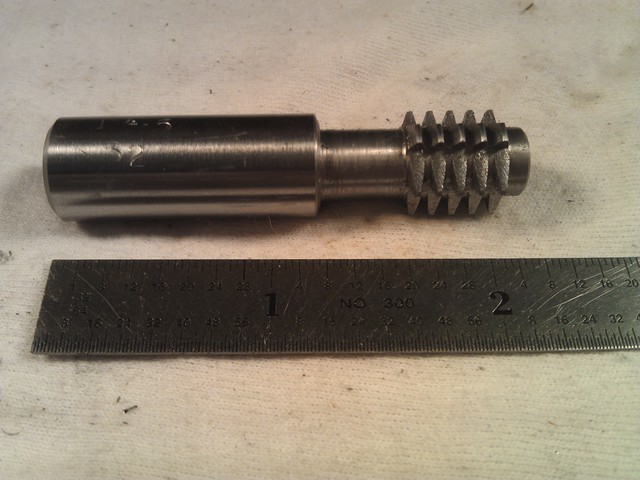
cutter infeed=1DP+1.25DP=2.25DPNow to hard numbers. To test these formulae, I'm going to try to replicate a gear I already have. I wanted to replicate one from my lathe, but I don't have any tool steel big enough to make a cutter that will cut teeth that deep. Instead, I bought a gear to replicate. It's a 22 tooth, 32 diametral pitch, 14.5° pressure angle gear.
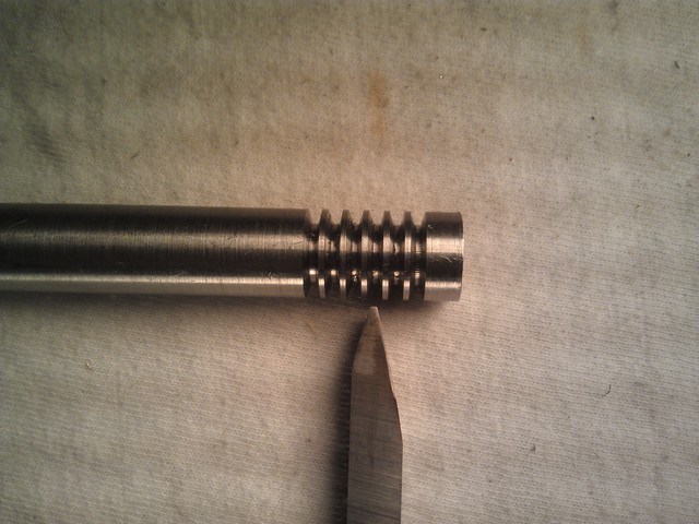
Step 1: Grind 29° single-point cutter.
Despite the talk of "simplicity" and "sharp peak" above, a sharp 29° is a little unworkable for the single-point cutter. Instead, I'm going to grind the tip flat. Just keep track of how much you take off and shorten the depth in step 2 by that amount. As long as you are above the addendum+dedendum amount, it's fine. The most you can take off the tip is
max removal=sharp groove−cutter infeed=π4DPtan(PA)+1.25DP−2.25DP=π4DPtan(PA)−1DPPlugging in the numbers for my test groove, I can take up to .0637" off the sharp tip.
If I had a tool and cutter grinder, I could just do that. However, I'm working on a bench grinder by hand. So I'm going to do a little outside-the-box thinking. A 29° included angle tool with a flat tip is identical to an acme threading tool. An acme thread gauge has tip widths built into it. If I can find one of those smaller than the max tip width of the above calculation, I can aim for that.
.0637" of tip length translates to .0329" of tip width. Machinery's Handbook says that a 10 TPI acme thread has a root width of .0319". So, if my ground single-point cutter fits in the 10 TPI acme thread gauge slot, and doing a little trig, I know I've ground off .0617" of length.
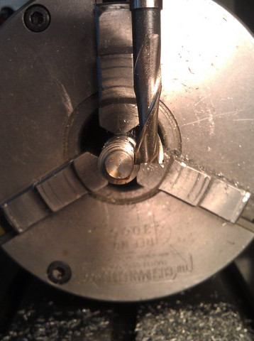
Step 2: Using that tool, cut several grooves in some tool steel
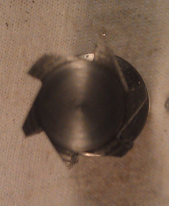
Step 3: Cut teeth. There are a few constraints here. First is that the entire shape of the cutting tooth is "revealed". second is that you need relief at the top of the cutting tooth. Third is that you need relief on the face of the tooth. And fourth is that you don't want the entire tooth so thin (in the direction of rotation) that it snaps right off.
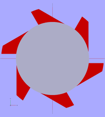
I did some trig to figure some optimal angles, but it's too complicated for how little it matters exactly what you do. Instead, I made some models in openscad to verify that the number I wanted to do (6 teeth) actually worked pretty well.
Step 4: Heat treatment.
I don't have any pictures of this because both my torch and camera require two hands. However, I set up a "cavity" of fire bricks, set the gear cutter inside and played a propane torch the working end for a few minutes. It took about 5 min before it started glowing. When it was bright red, I pulled it out and swirled it around a can of vegetable oil.
At this point it is hard enough that a file skips across it. Then into the kitchen oven for tempering at about 450°F.
Things for Next Time:
Now to actually using the gear cutter.
The gear I want to try to replicate is a 22 tooth, 32 diametral pitch, 14.5° pressure angle gear. The PCD is therefore 2232 inches. The addendnum is 1DP beyond that, but remember this is the diameter so there's an addendum "on each side", so
gear blank diameter=2232+21DP=2232+232=22+232=.750(As an aside, this explains the oft-heard, never-explained "number of teeth + 2, divided by the diametral pitch" rule for figuring out gear blank diameters.)
I'm not going to go into exactly how I turned the right thickness and diameter, since this is basic machining. I'm also not going to go into workholding, since that's going to vary with gear size, number of gears being cut, materials, time, etc.
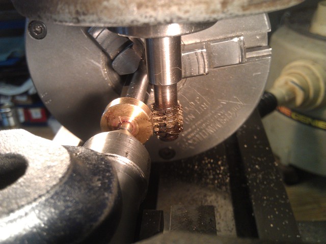
I went to full cutter depth (2.25DP=2.2532=.070) in one bite. This turns out to be really easy, despite the relatively deep cut, because after the first tooth all the teeth are partially pre-cut.
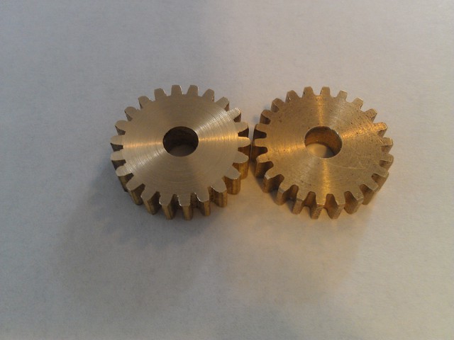
I only did one "pass" (as defined above, in terms of moving the relative gear/cutter positions to get a better approximation of a perfect involute). I'd like to make a couple of the same dimensions but different numbers of passes. This one feels like it has flats on the faces and I think I can even see them if I hold it up to the light.
The distance between two gears is PCD1+PCD22, which in this case is just 2232=.6875. So I drilled two holes at that distance and put some dowel pins in there as axles.
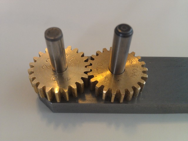
They don't quite work. I can actually force them to mesh, but they won't turn. However, I can feel them "clicking" back and forth in two very close positions, so I think I'm feeling the low-res involute approximation faces. With more passes, we'll see what happens.
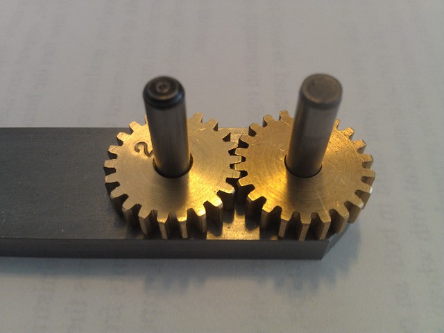
Here's a two-pass (as defined above) attempt. For the second pass, I rotated by "half a tooth". On my dividing head, each tooth was 45 holes, so I just rotated 22 holes. Then I moved the table in Z by 2245∗.098=.048, or "half" the distance between the single-point cutter teeth.
It works perfectly! I don't feel the "clicks" and the gear will spin freely when I flick it with my finger.