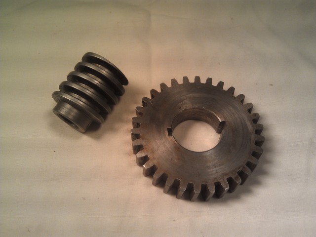
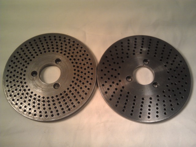
I have a very small mill. The clearance between the bottom of the spindle and the top of the table is just 8" and that's without any tooling, vice or work in there. Once you start adding that in, the space disappears very quickly.
Finding a dividing head that will fit in that space is difficult, so I decided to design and build my own. I had a $1 worm gear and wheel as a flea market find and some used dividing discs that I could design around.
 |
 |
My first design seemed simple, but I kept having to add nubs here and there to solve various problems. Also, I finally realized that putting the worm outside meant the unit could be smaller.
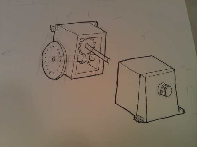
first idea
|
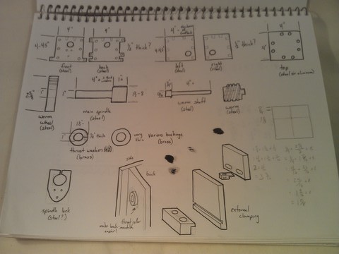
first idea gets complicated and oversize
|
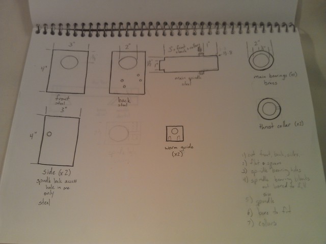
simpler plan
|
The drawings are deliberately rudimentary. I've found that thinking too far ahead causes more problems than it solves.
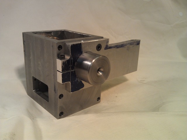
The first step was constructing the main box. A lot of people start with a cast block for this, but I don't have one. Material is generic "steel" from the scrap pile. The window in the side is mirrored on the other side and is to accommodate hold-down clamps.
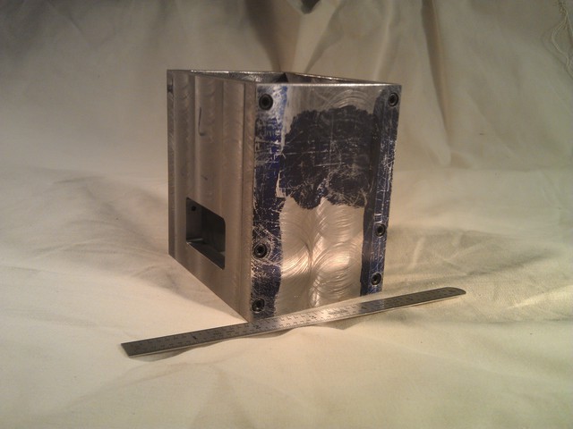
This box needs to have a spindle hole bored through it and bronze bearings pressed in. However, the spindle size matters while the spindle hole only has to match the spindle, so I decided to do the spindle first.
I had a 2"x~2' scrap that I was given. It was nice and straight and round, but covered in irregular blobs of paint (it used to be a roller stand). This is the largest piece I've ever had in the lathe before. I bought the steady rest just for this job, although I'm sure I'll use it again.
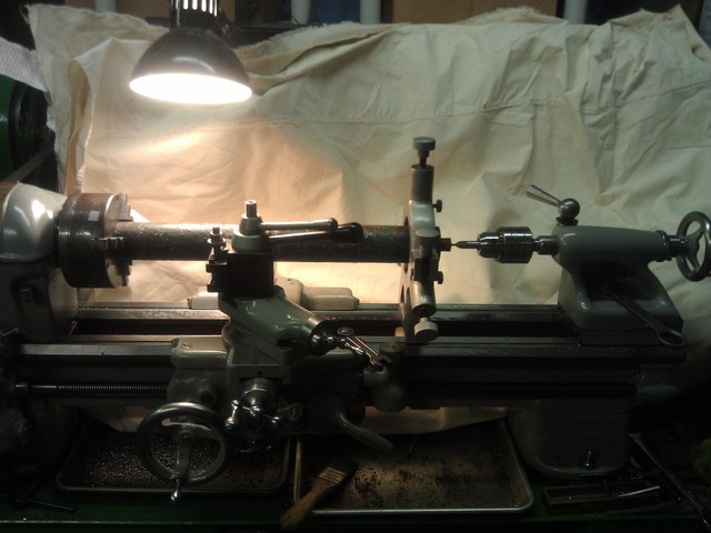
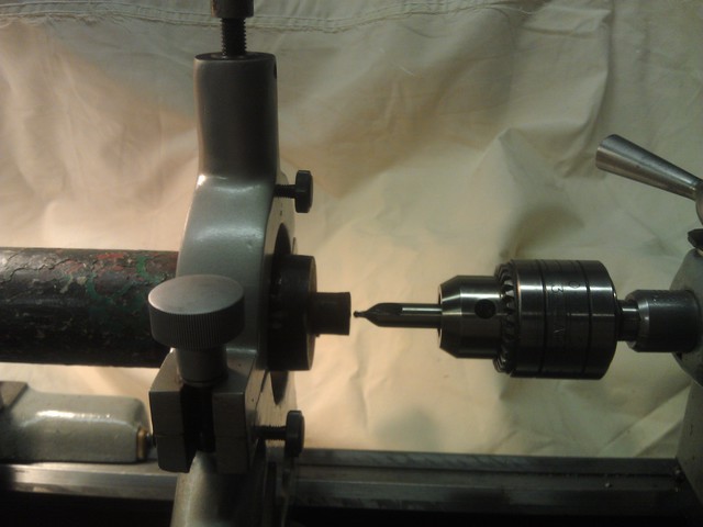
The length worked out just about perfect.
My lathe spindle is threaded 1 1/2"-8, so I'm doing the dividing head spindle to match. It's kind of dumb, because my smallest lathe chuck is a little oversize for the dividing head, but I think any other decision is going to end up being even dumber. Eventually I'll have a larger mill and I can beef up the dividing head a little and re-use the same spindle.
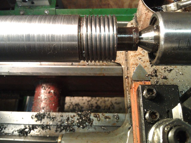
I'm also leaving the 1 1/2" diameter the full length of the body in case I want to put a morse or collet taper in there later.
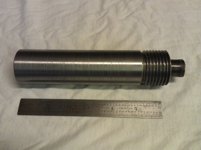
The spindle isn't done, but before I take any irrevocable further steps, I'm going to work on another piece.
Also, while getting the 2" raw stock down to 1 1/2" I did a lot of experiments with speeds and feeds and tool material and geometry. This was about as good as I could get it. I also sanded it, so it's actually nice and smooth, but you can still see some lines.
The next thing to work on for a while is the spindle bearing.
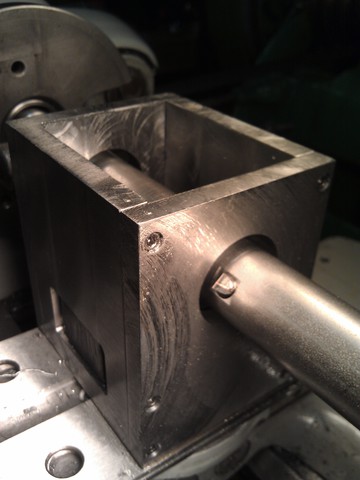
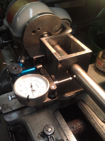
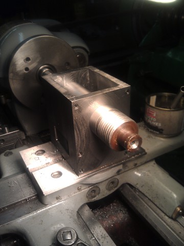
For this, I did line boring. The part is mounted to the lathe's cross slide and a cutter is held in a bar held between centers. The middle image here is showing one of the steps to adjust the cutting radius. The last image shows the spindle in place. I was testing to see if I could hit a pre-arranged diameter, and it came out really well. There's just the tiniest amount of radial play.
I'm going to be boring these holes bigger to accept a bronze bearing. If this spindle were going to be rotating a lot, that would be important. In this case, I could probably keep the steel-on-steel contact, but If Anything Happened I'd have to re-make either the body or the spindle. I'd rather just replace a bronze sleeve in that case. Plus the colors will look cool.
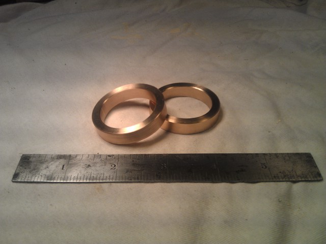
The bronze spindle bearings are a simple turning job. Although this metal was a lot harder than I expected, having only worked with brass before, not bronze. I ended up unable to part them off and sawed instead.
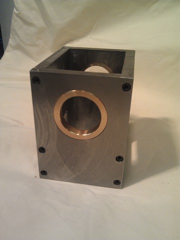
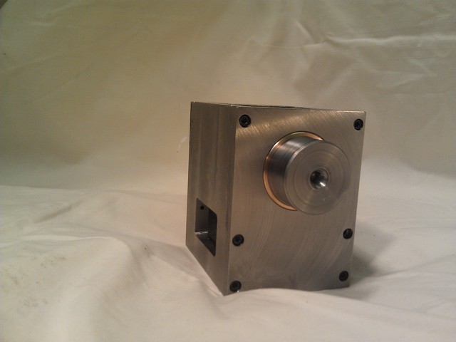
Pressed the bearings in (a nice, smooth .001"-.002" fit pressed in with a bench vice, as I have no other press). Then mounted back in the lathe as above to bore them out to 1.500" for the spindle. I don't think I could have hoped for a better fit on the spindle. Very free turning with virtually no radial movement.
(Note that this is the spindle's back end for beauty's sake. I haven't finished off the spindle yet because I'm not willing to lose my centers yet.)
I'm a little nervous about if I ever have to disassemble the box and it won't be perfectly aligned anymore when it goes back together. However, if I tighten down the screws with the spindle in place, I think that will align the front and back and I'll be OK.
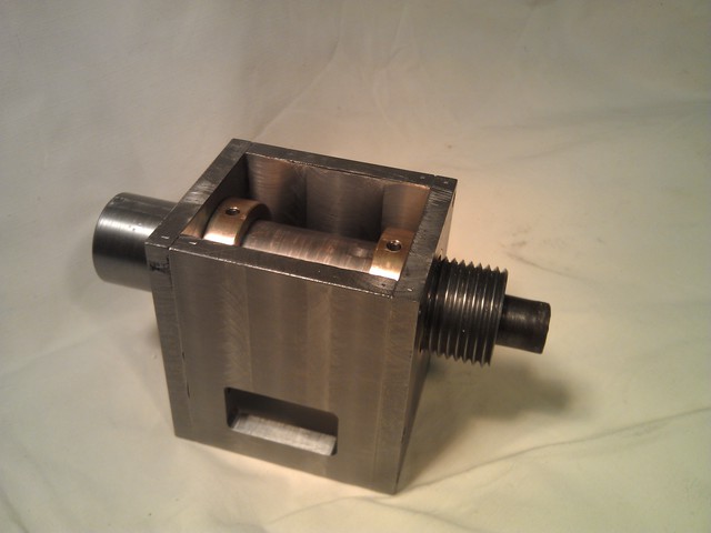
Added a couple of simple thrust collars to constrain axial motion. I was going to make them a little fancier, but making my own thrust collars for my homemade dividing head is already enough superfluous work.
Next up, a spindle lock. I'm leaving it long because it's also going to serve another function that you'll see later. Because of the awkward shape, my first choice would be a boring head in the mill, but I don't have one. Second would be in the 4 jaw chuck on the lathe, but it's long and the hole is near one end and therefore it wouldn't fit. Instead, I had to come up with some way to do this in the mill after all.
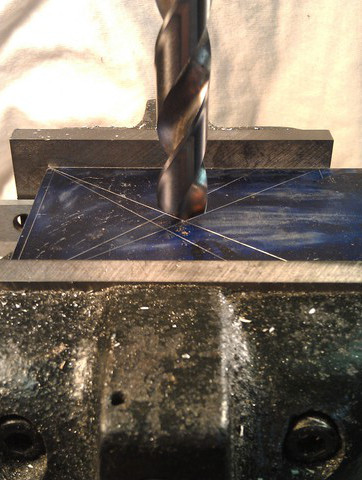
First, drill with the biggest drill bit I have.
|
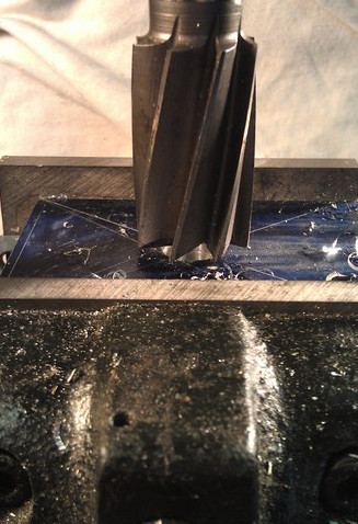
Then try to open it out with a large shell mill.
|
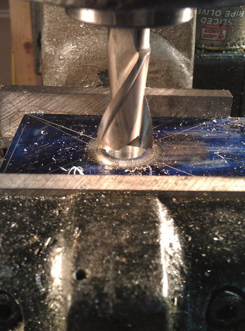
That was too big of a jump so back down to a 3/4" end mill.
|
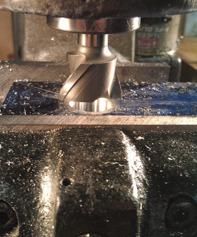
Another, bigger end mill..
|
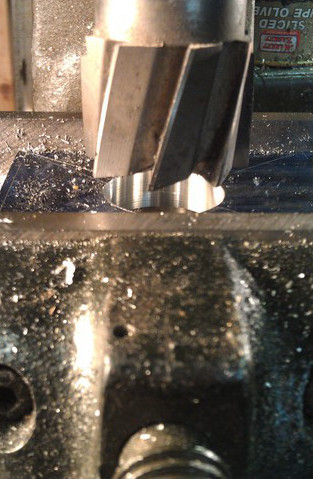
Now the final size shell mill?
|
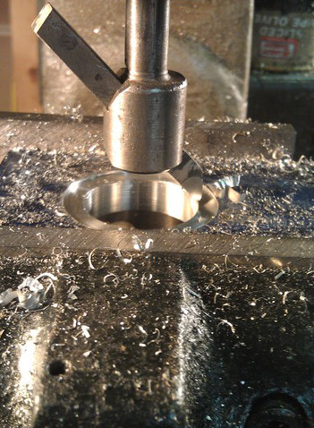
Nope, still too big. Several fly cutter passes to open it out.
|
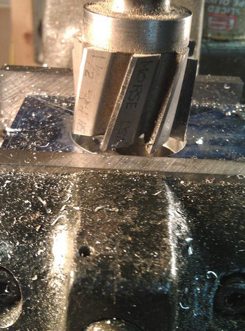
Finally, the 1-1/2" shell mill can take it to size.
|
A little more work to create the locking function and attach it and I have a spindle lock. The extra length is for a future step.
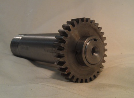
Some basic machining here to reduce one end of the spindle to fit the worm wheel, cut a keyway and fit a collar to hold it all together. The only wrinkle was that the key I bought at the hardware store was so far undersize (.005") and my milling cutter so far oversize (.003") that the worm wheel just rattled around on the shaft, so I made my own 3/16" key.
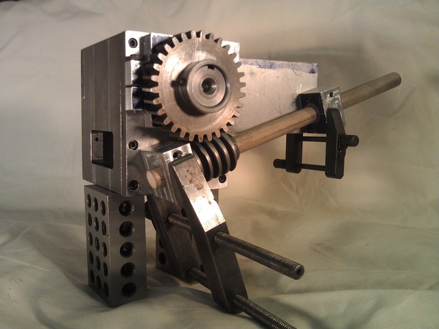
I don't want to try to measure a bunch of 3D stuff and do trig to figure out where to put things, so I made some simple bearing blocks and a wooden dowel as a mock input shaft. This let me mess around with a bunch of angles and ideas. I think the bottom bearing block will remain (but cut down a little), while the other one will be replaced with something else.
This is also the first time I've seen the dividing head actually "working". That is, I can turn the dowel by hand and the main spindle rotates very slowly. No reason it shouldn't, but it's neat seeing a vision come to life.
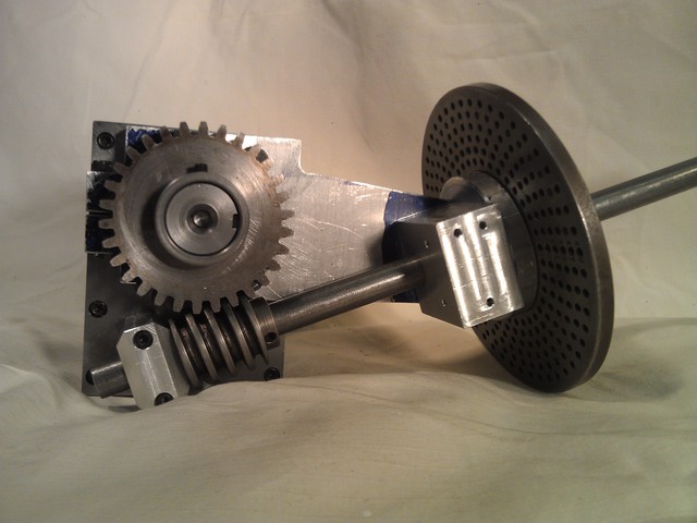
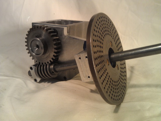
Here are those same parts attached, as well as some work done to mount the dividing discs. The input shaft is just sitting there as raw stock with no work done on it whatsoever.
The arm extending out from the body to the dividing disc looks a little long to me. On the other hand, it might be nice to be able to mount the dividing head on the back edge of the mill table and still reach the input handle. I was really constrained as to the angle I could put the input shaft.
Also, the block right behind the dividing disc is pretty blocky. I'm going to lighten that with some chamfers, but the reason it's so big to begin with is that I wanted to put enough screws in there to make sure it didn't bend as I crank the handle around.
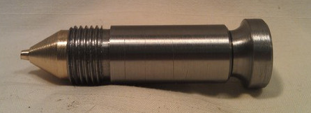
I avoided the input shaft as long as possible because I didn't know how anything was going to attach. I figured if I had the things I was going to attach in front of them, figuring out the attaching part would be easier. So I started from the "other end" and made a handle.

Pretty close, now. Got a crank in place and attached to the input shaft. The shaft isn't cut to length, retained axially or pinned to the worm gear yet, but those are all relatively easy tasks. ("Retained axially" meaning if I pull on the handle, the entire shaft is likely to pull out rather than simply disengaging the handle detent pin from the dividing disc.)
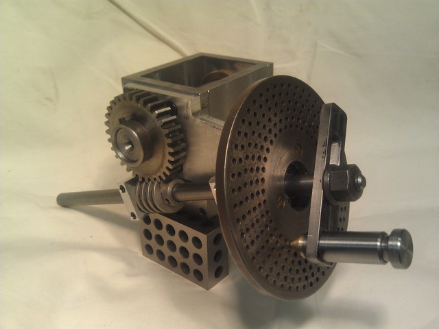
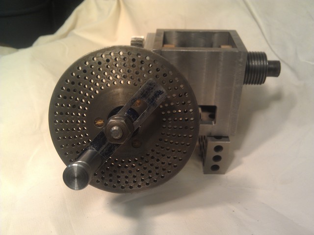
You'll note quite a gap between the input crank and the face of the dividing disc. This is on purpose. I'm leaving room for some sector arms. They are kind of a convenience thing, so I'm going to use the dividing head without them at first. But I definitely want to make them.
Also, the handle spring has a little too much pre-tension, so I need to either shorten the spring or lengthen the handle. I have a new handle design in mind, but I want to get the whole thing working before I tweak it.
And here it is, basically complete.
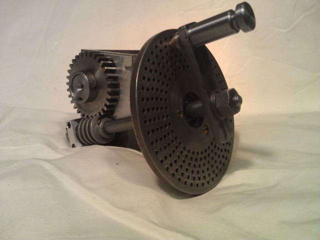
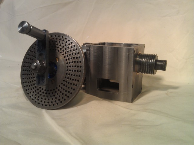
Biggest thing missing: Sector arms.
Biggest existing feature that needs fixing: Turning the crank unscrews the end of the plunger. Need a new plunger design.
A true spindle-lock to prevent any rotation of the spindle when removing the dividing arm.